

The technical environment of High-Speed rail
Though every country has its own model of high-speed models vary from country to country, high-speed lines around the world share comparable technical and functional characteristics. Above all else, high-speed lines retain the fundamental specificities of all railways, and their mission is to a vehicle’s wheels over rail, using sleepersto hold gauge and maintain alignment. However, high-speed is distinguished by a series of details that, while they allow for high-speed trains to run on conventional tracks, generally render high-speed rail lines inaccessible to conventional trains. These particularities specific to high-speed rail fall within the area of infrastructure – route selection, authorised gradients, curve radius, quality of material, rail gauge, track equipment -, or in the area of rolling stock – energy source or on-board systems. Both areas are closely linked.
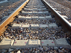
RAIL GAUGE
Gauge is generally the same as that of the conventional network to which high-speed lines are connected: “normal” track measuring 1,435 mm in most countries (Western standard), or “wide” track measuring 1,520 mm in Russia. However, high-speed lines in Japan and Spain also have “normal” track, though the conventional networks of these two countries are respectively “narrow” track measuring 1,067 mm and “wide” measuring 1,668 mm. In Spain, trains equipped with variable gauge axles are able to run on the two networks.

ROUTE
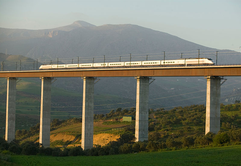
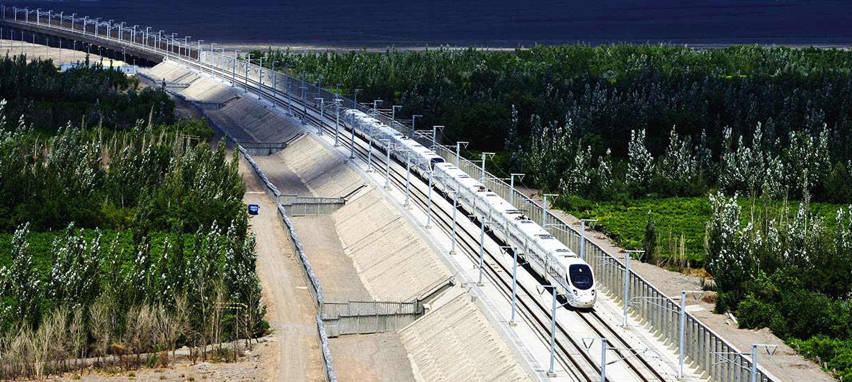
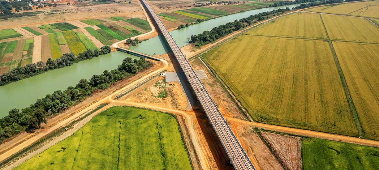
High-speed lines are characterised by large radius bends and ramps that are more significant than on the conventional network, made possible by the dedicated rolling stock design. These lines have absolutely no level crossings. As for crossings (switches), their geometry and mobile core must allow for passing at high speed, which would not be the case with “short” switches. In addition, as speeds are higher, so are the pressure waves generated by the train.
Consequentially, this requires increasing the distance between tracks as well as reworking the shape and dimensions of tunnels. Finally, on rail lines dedicated to high-speed trains, at least those trains designed by the French, axle load is limited to 17 tons in order to limit the dynamic stress of trains on the track.
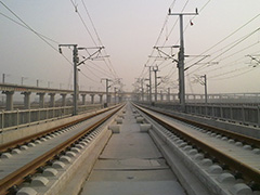
BALLAST OR CONCRETE
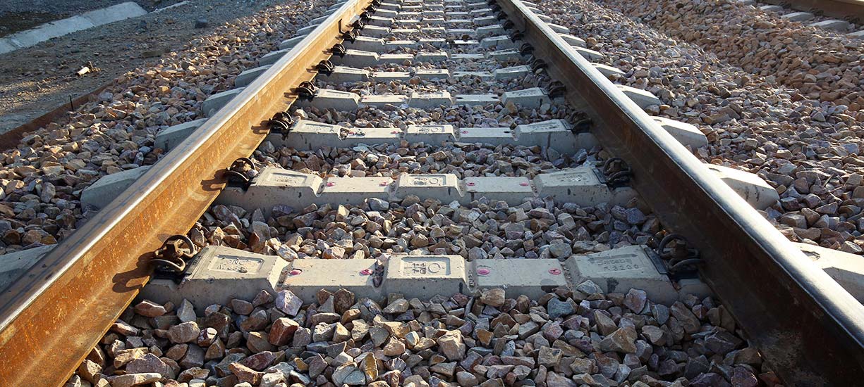
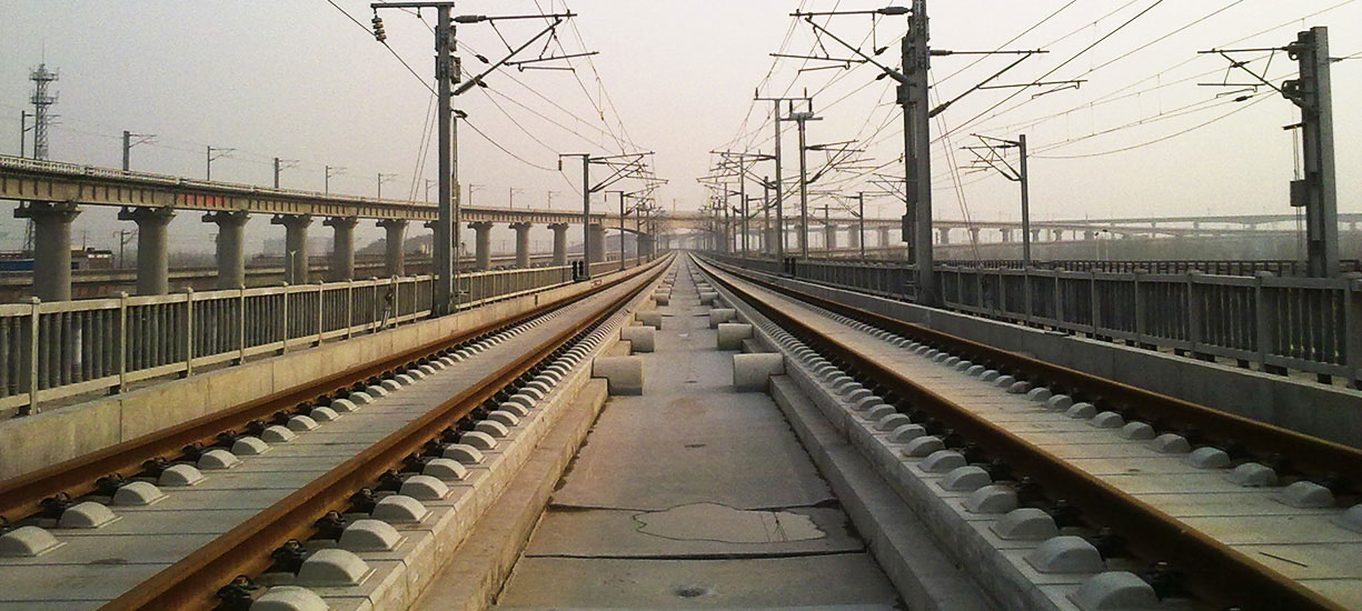
In the same way as for conventional lines, track can be laid on a layer of ballast in the most traditional method, or integrated to concrete slab, a method used for Chinese lines among others. Considerations for the choice of slab track or track laid on ballast include the availability of materials near construction sites, the nature of local terrain, and the necessity or lack thereof for engineering works.
Ballast is the most economical method, with the exception of engineering works. It offers the advantages of implementation flexibility as well as rapid installation and good potential for recyclability. Ballast also absorbs noise better than concrete. Its lifespan, however, is shorter, and maintenance is required. Ballast is constituted of light grade crushed stone, which, if poorly stabilised, risks being displaced by the passage of a high-speed train, causing damage to the train and to surrounding areas.
Slab track incurs no risk of displacement. Its advantages: less volume required to lay the track, cleanliness – no dust -, and an improved security for the evacuation of passengers. Slab also offers the possibility of being formedseparately on both sides of the track, to limit the consequences of any eventual derailment. Maintenance operations are quicker, easier, and access is facilitated for vehicles. Slab track has been adopted in all major rail tunnels, such as the Channel Tunnel, the Gotthard Tunnel in Switzerland, and the Sikan Tunnel in Japan. In the principal method of laying track on concrete, known as Rheda 2000, twin block sleepers – where two concrete blocks that support the rails are connected by a metal spacer – are put into position on a metal framework using provisional rails before pouring the concrete; the definitive rails, on which trains will run, are then laid on top of sleepers that are nearly fully-submerged in concrete. The other type of slab track is FFB (FesteFahrbahnBögl), which is implemented in the form of prefabricated slabs.
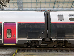
MOTORISATION AND TRACTION
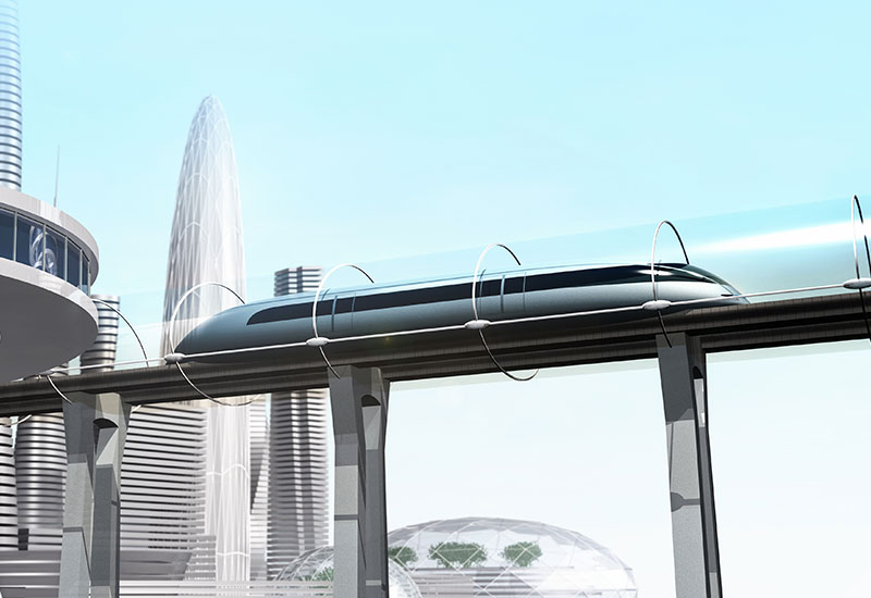
There is nothing revolutionary about traction:the rotation of driving wheels is what propels trains forward. Historically, linear motorisation - which turns the system into a gigantic electric motor, using the train as a rotor and the track as stator – has not been the system of choice for high-speed rail trains, though it has been adopted for magnetic levitation (Maglev). In the field of motorisation, two schools of thought are diametrically opposed: concentrated power, in which motor bogies are placed under two drive units without passengers, at either end of the trainset (TGV, first generations of ICE, ETR 500…), and distributed power, in which motor bogies are distributed under rail cars throughout the trainset to ensure passenger transportation (Shinkansen, ICE 3 and its derivatives, AGV, Zefiro…). In a very progressive manner, distributed power has replaced concentrated power (in Germany, in Italy, with Eurostar), but also for future generations ordered by SNCF (France) or Amtrak (USA). Alstom is currently preparing trains with concentrated power.
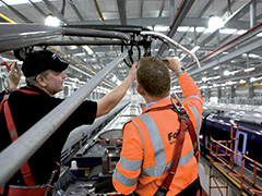
ENERGY
Since the advent of the oil crises in the 1970s, electric traction has become widespread in high-speed rail. Even if SNCF’s TGV 001 prototype was a high-speed turbo-train! Though voltage and the nature of current –AC or DC, with several possible frequencies – vary considerably from one conventional rail network to another, a certain normalisation has been established for high-speed lines with a power supply of 25 kV, and system frequencies of 50Hz or 60Hz depending on the country. There are however notable exceptions, such as in Germany, where high-speed lines have kept the same voltage (15 kV) and frequency (16,7 Hz), equivalent to that of the conventional rail network.
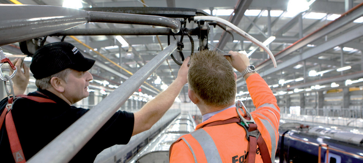
The first few years of experience on the French high-speed line, from Paris to Lyon, led SNCF to limit articulation of pantographs to assure the collection of current, in order to avoid the risk of breaking the catenary that provides power supply. This “extra” added on to the TGV implies that the catenary on high-speed lines would always be sited at the same height (5.28 m above the track, in this case).
SIGNALISATION
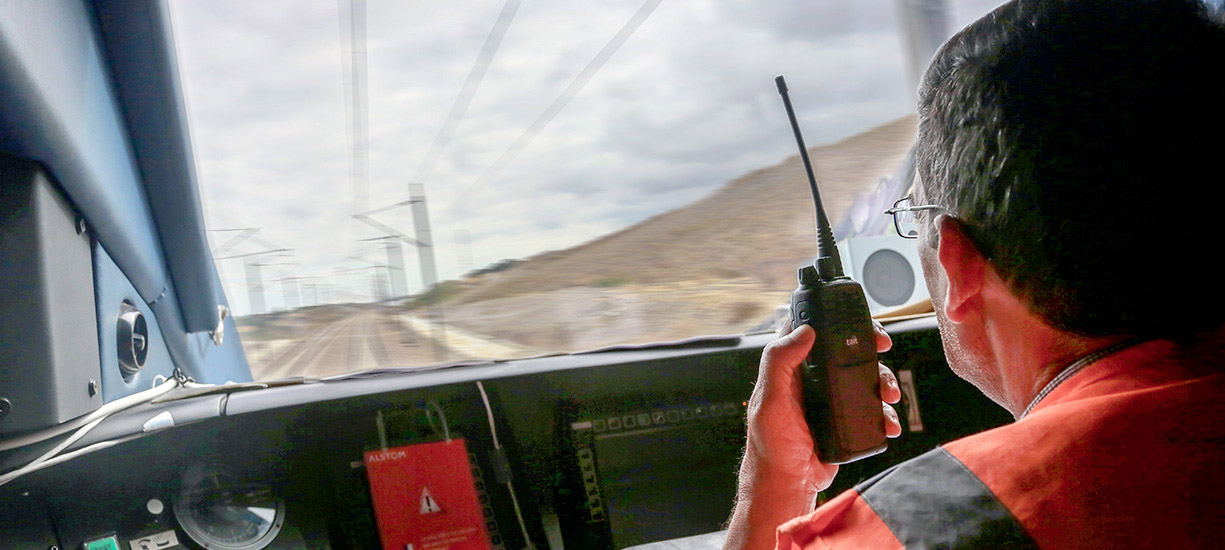
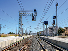
High-speed lines are visually identifiable by the absence of lateral signalisation. In high-speed, drivers do not have enough time to read conventional signals, which are replaced on the side of the track by “boxes” that mark the boundaries of track sections known as blocks. Speed limits in effect along different blocks are thus currently transmitted from the ground to the train, and are displayed on the driver’s cabin console. This in-cabin signalisation system is known as Cab signalling.In France, this transmission is known as TVM (transmission voie-machine), and was implemented on the Paris-Lyon high-speed line in 1981 (TVM300), then on the TVM 430 on the LGV Nord line in 1993. Today, in Europe, the ERTMS /ETCS levels 1 and 2 systems are obligatory for any new high-speed line design or major upgrade for existing lines. The replacement of conventional signals by trackside boxes will thus be less and less unique to high-speed lines. Level 2 ERTMS, which is operational on certain conventional lines, does not use lateral signalisation.
